Search This Blog

Friday, 18 August 2017

Replacing the Under Saddle Pickup on an Electroacoustic Guitar

Over the last few months the pickup on my guitar has developed an unpleasant distortion. The A string produces a gritty buzzing sound. At first it was a very occasional, and intermittent problem. I thought I had cured it by putting a shim of paper between the saddle and the pickup under the A string, but the sound came back.


The guitar is a Tanglewood Odyssey cut-away. It is a "bowlback" design with a fibreglass back - I bought the guitar back in 1992, so it has done good service, but replacing the whole guitar is an expensive proposition. So I started reading-up about under-saddle pickups on the internet. The name ARTEC kept coming up, and their pickups looked very similar to what was fitted to my guitar.

Artec website.

I was particularly attracted to the SF-607 model because of this phrase " It reduces buzzing sound caused by curved bottom of saddle or rough surface of pickup cavity on the bridge of guitar. " - I suspect this may be the "buzzing sound" that I have been hearing, or else the pickup has developed a fault. Unfortunately the Solidflex pickups are not at widely available on E-bay as the PP and PG versions, but I found one in Singapore for about £12 and made the purchase.


The SF-607 is physically very similar to the pickup I took out. It is about a millimeter shorter, but the spacing of the piezo blocks is exactly the same. The 2.5mm jack-plug is finished more neatly than the old pick-up with a metal cover and gold plating on the contact surface. In the photo at left, the new pickup is at top and old one below


The pickup strip is blue and branded, the old one is covered with plain black heatshrink sleeve, but the width and thickness I measured to be within 0.1mm of the original. This was very useful because it meant it was almost a "drop-in" replacement. I say almost because the original was a snug fit in the slot, which required a little judicious filing with a needle file to accept the new pickup. I expect I could have forced the new one into the slot, but I wanted to be able to get it out again if I had to !

The 2.5mm plug means that there is no soldering of wires - and the preamp and EQ unit in the guitar seems to work just fine with the new pickup. Here are a few more pictures:
 The pickup goes underneath the white saddle, which is a hard plastic, or bone material set in a slot in the wooden bridge of the guitar.


A hole is drilled at the bottom end to allow the screened cable of the pickup to pass through to the inside of the guitar. The hole is just big enough to allow the 2.5mm jack plug to pass through. This picture shows the old pickup lifted out of the slot, and the shim which I had added to try and fix the distortion problem.


The new pickup just plugs into the preamp unit. Remember to tidy and tape down the wires inside the guitar before putting on the new strings - otherwise they may flop about and rattle when you play it. I used "gaffer tape" (otherwise known as "duct" or "duck" tape).

It is a useful opportunity to clear the dust out of the inside of the guitar - it had got decidedly mucky in there!
Here's another picture of the EQ unit. - the battery holder and front panel is separate, and goes on the outside of the body, the screened metal box is on the inside of the body, and when the screws are tightened it all clamps up tight in the side of the guitar.

I couldn't photograph that operation because I needed at least three hands to hold the EQ unit, front panel, guitar, screw and screwdriver - I didn't have any appendages left with which to operate the camera.


So does it work?
Yes it does, but it is different to the old pickup. The output is lower and there is a bigger variation in output between the individual strings. The A and D strings are louder than the others.

Here is an image of the six strings plucked one after the other and recorded in Audacity, first with the old pickup:

You can see the distortion on the "A" string, as the envelope looks "broken".

And then with the new:

The output is lower, overall, but the A string and D string are strongest. I estimate the top E to be about 6dB down, but the A string seems to be as strong as the old pickup. The good thing is that the output is clean and distortion-free. So I shall leave the new pickup in place for the time being and see how we get on with it. I will have to crank the volume up on the amplifier a bit to compensate for the lack of output.

73
Hugh M0WYE


Thursday, 22 June 2017

Another Whistle

I've just made a second whistle, this one is longer - in the key of G and, this time, using the black PVC pipe. I made the fipple block a bit longer and cut it at a sharper angle. This makes it a bit easier to play in my opinion.

If you didn't read my last blog, these are "penny whistles" made to the design of Guido Gonzato.

The black pipe makes a perfectly serviceable instrument, but it is much harder to see the pencil marks, and, conversely it shows the scuff-marks from sandpaper much more clearly! A strip of masking tape along the tube was useful to mark out the positions for the holes.
Here's a picture of the two whistles together.
73 Hugh M0WYE

Saturday, 17 June 2017

Low-Tech Whistle

I've got one of those cheap "Generation" tin whistles in the key of "D". It's quite fun to play, but it is quite high and squeaky and when I try to play with other instruments, it is horribly sharp. I like the sound of the lower pitch whistles, such as you hear played on tracks by Capercailie and on the Transatlantic Sessions television programs, but, although not very expensive, still looking at upwards of £50.

But I found an interesting website by Guido Gonzato here: Guide to making low-tech whistles

Now I have found designs for whistles before, but I have had difficulty getting the same materials as were used in the original. If you substitute a different type of tubing it has an affect on the length and hole position. But I found 2 meter lengths of this 20mm diameter PVC pipe in B&Q and Wickes for 99p and 18mm diameter hardwood dowel which can be made to be a snug fit inside by sanding off about half a mm.

So today I made one, and I am very pleased with the result (photo left). I won't go into detail about how I made it because Guido's instructions (in the above link) are very detailed and I followed them very closely.

I made the Alto B-flat instrument, and I found that I needed to leave the tube about 1mm longer than was specified in the diagram.

In fact, because my tube started out quite long, I checked his overall lengths at F#, G, G#, and A and found they all needed to be 1mm longer than specified - that probably comes down to the type of tube, he says "not all PVC pipe is created equal".

So I wanted to upload a sound-sample for you, but I don't see a way of doing that on Blogger, so it will have to be in the form of a video ...
Sorry I'm playing it a bit like a recorder, it's just to give an idea of what it sounds like! Guido has some much better sound samples on his website.

I'm intending to make some more of these, in different keys, and perhaps even longer and more mellow :-)

Anyway, if you like making simple musical instruments, I encourage you to have a go at making one of Guido's low-tech whistles.
73
Hugh M0WYE


Saturday, 10 June 2017

Lidl's Vice

I've got a variety of bull-dog clips, clothes pegs and "extra hands" to hold small items when soldering. I did have a small table-top vice, but my son "borrowed it" and it has obviously proved very useful to him ... haven't seen it since :-)

When I saw that Lidl's were offering a table-top vice for eight quid, I thought I would give it a try.
Lidl's Table Top Vice Offer.

Some of their tools are very good value for money, occasionally I have wished that they were better quality!
This product seems ok ... but there are some important things to be aware of. One is quite obvious when you pick up the box in store - it isn't very heavy! It is not made of steel, it is made of an aluminium alloy (clearly stated in the instructions) and this means the casting is not going to be very strong. Don't expect to use it like an expensive Record vice for hammering and bending thick metal, it will break.

The aluminium will likely not be as hard-wearing as steel would be.

The main tommy-bar, used for tightening the jaws of the vice is quite nice, with a detent at each end, so that the bar clicks into place at each end of its travel. However I found that all the screw threads felt rough and "graunchy" - not smooth at all. Although the instructions make no mention of lubrication, the first thing I did was to apply grease to all the threads and the grooves where the moving jaw of the vice slides. I also greased the ball and socket and now it feels much nicer to use.
hopefully that will extent the life of the threads a bit too. Time will tell.

The vice is supplied with soft, plastic covers for the jaws, which could be useful for holding some items, but will obviously be useless for soldering, because they will melt! Underneath the plastic covers are smooth metal jaws, one of which has two grooves at right-angles. The grooves are for holding round objects.

Supplied with the vice is a clamp for holding tubes of between 38 and 43mm diameter. This seems rather a limited range to me, and it is complicated to fit the tube attachment. To do this you have to remove a the jaws, which requires the use of the supplied hexagon wrench. However, the fact that the jaws can be removed does allow for the user to create their own attachments.

I'm thinking that this will be very useful for holding plugs, sockets and circuit broards instead of chasing them round the bench with the soldering iron.

73
Hugh M0WYE


Sunday, 4 June 2017

Oh bother ...

Wondered why I had no audio this morning. Went to unscrew the cover on the mic jack and it fell apart in my hands. Yuk! cheap plug. Now replaced by a gold plated on - hopefully last a bit longer!
73
Hugh

Wednesday, 31 May 2017

TYT MD380 Hands Free Kit - in use

Thanks to Colin G0PHO and Bradley M0XBW for the on-air test today - and enjoyable mobile QSOs! I can confirm that the hands-free kit is working well.
I thought I would add this photo of the radio in the car, although it is a little confused because I still have the wiring for the FT60 handheld here too. There are two toggle switches taped to the cigarette lighter plug, bottom right. the left hand one is for the DMR radio.
The "well" in which the radio sits is in the centre console and the TX/RX switch is just in-front of the gear lever, so it is easy to find without looking.
I use the internal battery of the radio. In the old days you could get more RF power out by running your handheld on 10 or 12V derived from the vehicle supply, but the modern radios produce just as much output when running from internal batteries. Also, this approach prevents alternator whine and ignition noise from the car electrical system appearing on the transmitted or received audio.

The cigarette lighter plug here is a mobile phone charger and nothing to do with the radio set-up.

There are a couple of general comments I would like to make about the TYT MD380, in case you are thinking of getting one. I find the display quite difficult to see out doors in daylight - quite impossible if the sun is shining on it. The colour display is very pretty indoors, when the backlight is on, but goes completely blank when the back-light switches off. I find I am constantly twiddling the volume, or pushing the power up-down button just so the light will come on and I can read the screen.

Also the radio is supplied with a charging stand - with a nice LED that is red when charging and goes green when it is cooked. I like that, but it is powered by one of those horrid little plug-top power supplies and it generates S9 noise right across the 50MHz band - ughh! I don't think it has any filtering in it at all, such a shame for an amateur radio product, and makes you wonder about the safety of the device if they can't be bothered to meet EMC requirements. So no chance of using six meters when the radio is charging.

73
Hugh

Sunday, 28 May 2017

Hands-free kit for TYT MD380

I have finally got round to it!
To my shame I see it was nearly a year ago that I worked out the microphone and speaker connections on my TYT MD380 handheld - see the blog here:
Mic and speaker connections for TYT MD380

I have a home-made hands-free set up for operating mobile with my analogue handheld (an FT60E) and I would like to use something similar for the digital radio.

The microphone is a small electret condenser capsule, mounted on a microphone boom of galvanised iron wire (coat-hanger wire!) which is attached to a baseball hat. The microphone is quite close to the mouth, but not directly in front to avoid breath-blast. When I made my first version, I stitched the wire to the front of the cap, which was quite time consuming. The current one is glued to the back of the brim with hot-melt glue. Not very pretty, but quite quick to do.

The transmit switch is a toggle switch that is taped to the side of a cigarette-lighter plug that is located very conveniently beside the gear-change stick. This makes it very easy to flip between TX and RX without taking my eyes off the road. And also doesn't involve drilling any holes in car.

I use a Diamond dual-band mobile antenna on the motor car, mounted on the tailgate and connected to the radio via RG58, a BNC and one of those BNC - SMA adaptors.

On the radio, under a plastic cover on the right-hand-side are two sockets, a 2.5mm diameter jack and a 3.5mm diameter jack. These are dual purpose, the 2.5mm one is used for the speaker connection, the 3.5mm is used for the microphone, and the radio is put into transmit by connecting the ground connection of the microphone to the ground connection of the speaker. The two sockets are also used for a USB type serial link for programming the radio - so don't connect to the unused terminals on the connector they are for data transfer. I used a cut-down, ready-made,  2.5mm audio cable, to avoid soldering to a rather fiddly plug.


So here is a diagram showing the connections to the radio. Note how the microphone positive is connected to the ring of the 3.5mm jack, not the tip. Leave the tip unconnected. Also leave the ring on the 2.5mm jack unconnected, these are the data connections. See how the transmit/receive (PTT) switch is wired between the speaker and microphone grounds. It is important for the microphone to be wired the correct way round, because the radio provides power for the FET amplifier in the capsule.
Here is a picture of the wiring before I covered it all with electrical tape. We don't want any short circuits. But it is always best to test it all before covering it with heatshrink or insulting tape.


Here is the complete set-up. A more glamorous baseball cap would do wonders for the appearance of the equipment ... so would a more glamorous radio ham.


A note about the loudspeaker: I use a cheap car radio speaker because it is in a nice plastic pod, which I can put on the centre console of the car. The radio specification calls for a 16 ohm impedance loudspeaker. The car radio speaker is clearly a 4 ohm part. The radio does seem to work ok with an 8 ohm speaker, but I thought 4 ohms was pushing it a bit. I used a transformer to convert the impedance. I am using just the secondary of an audio output transformer. The winding has a centre-tap and I am using it as an autotransformer. The radio is connected across the whole winding, the speaker is connected between one end and the centre-tap. This gives a 4:1 impedance conversion. The primary of the transformer is left unconnected. Hopefully you will be able to find a more suitable speaker and not have to bother with this!

Testing: I first checked the speaker connections, plugging the 2.5mm plug in and listening to the World-wide talk-group on the local repeater. When all was working on the receive side, I made sure the TX/RX switch was "off" and plugged in the 3.5mm jack. Now, on our local repeater GB7AS, we have a special Talk-group on Slot 2 which echos back the transmit audio after a short delay, for people to test their radios. This is called TG9990 Echo Test. If you don't have this, then you will have to get a friend to listen to your audio and check it is working well. you can see if the TX/RX switch is working because the LED on the top of the radio goes red in transmit.  Have fun!
73
Hugh M0WYE


Friday, 26 May 2017

Ermine Moth


I notice that there are a few places along my route to work where the hedge is festooned with what looks like spiders web.
A closer look reveals that the culprit is not a spider, but lots of caterpillars.
This last happened in May 2011 (I still have the photos I took then!), and a bit of research then revealed that these are ermine moth caterpillars, and their host plant, is the spindle tree.
On the Wikipedia page there is a picture of the moth, but I have never knowingly seen one of the adults.  https://en.wikipedia.org/wiki/Yponomeuta_cagnagella


The plant has been completely stripped of leaves, but in 2011 the bare twigs sprouted new leaves after the caterpillars had gone. It can't do the spindle tree much good, but it does seem to recover. So I hope it will do so again this year. I notice that the parts of the hedge which are affected are all close to telegraph poles - not sure if that is coincidence.

Since I travel this route almost every day, I think I would have noticed if there had been similar tents in the hedge between 2011 and 2017, but I don't recall seeing any. So that raises the question is this a regular event occurring every six years? or is it just the climatic conditions have been ideal for the caterpillars? At the moment ... we just don't know ...
73
Hugh M0WYE


Wednesday, 3 May 2017

Bass Pedalboard Microswitches

A bit more on the bass pedalboard project.
I tried some different switches ...

I found the smallest ones were the best. They are the quietest in operation.
They are arranged in pairs. The idea is to try and use velocity sensing - the harder the pedal is played the less time between the switch closures. That's the theory ....


In practice I found it quite hard to match the pedals, as the exact point at which the contacts close depend on the spacing of the pedal and positioning of the switch. my woodwork may not be good enough for this!
 Here's a very slow pedal press, at 130mS long gap between the two switches closing.
 Here's the fastest I could do by really stomping on it ... about 1mS. But here you can start to see the "switch-bounce". I will filter that out, but it may be hard to separate the "bounce" from the "stomp" at these short times.
Here's a medium sort of pedal press at about 15mS. There is a distinct logaraithmicness to the range of times I was getting. it will be a bit of a challenge to get the software to measure these times with out delaying the note-on command appreciably.


73
Hugh M0WYE
Emergency Light Power Consumption

I was given a couple of emergency lights which were being taken out of service because the batteries had deteriorated.

Emergency Light

I wondered about installing one above the stairs in my home, as it would be a useful safety feature in the event of a power cut. But how much power does one of these things use?


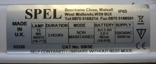
Manufacturer's Label - Spel
The "ratings plate" gave no indication. The 8 Watts referred to is the power of the fluorescent lamp - but that only runs when the mains power is off. There is no indication of how much power is used from the mains to charge the batteries.


Plug-in Power Meter
I decided to measure it using one of those plug-in mains power meters. And was alarmed to see a figure of 40 Watts displayed. Now later I realised that there was a very small decimal point in between the digits and the actual level is more like 3.5 or 4.0 Watts! But even that is still a significant amount of power when the device is on 24 hours a day, 7 days a week. It works out at 35 kilowatt hours each year - or a few pounds-worth of electricity.


Some of my colleagues suggested that the charge circuit would probably shut off once the batteries were charged, so then the consumption would drop. I took a look inside the case, but the circuit looked suspiciously simple - so how does it work?
 There is a mains transformer, and a watty resistor (R1). There is another, smaller transformer and some components that probably form a invertor circuit to light the fluorescent lamp. But there is very little in the way of logic circuitry - and the relay RL1 is conspicuous by it's absence!
Circuit Board
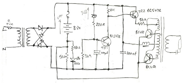
So after a few hours of work with a magnifying glass, and a resistance meter I worked out the circuit is as shown below.

Circuit Diagram
The mains comes into the mains transformer and passes through a bridge rectifier. The supply at this point measures about 10.3 Volts. The charge circuit is really simple: There is a 50 ohm wire-wound resistor which limits the current into the 3.6 Volt battery. There is a red LED across the 50 ohm resistor, which lights up to indicate that there is Voltage being dropped across the resistor, and hence current flowing into the battery. With 3.6V across the battery, there is 6.7 Volts across the resistor - using ohms law, the charge current works out to be about 134mA. With fully charged NiCds the battery Voltage will rise a little, but the charge current is unlikely to be less than 120mA. So the charge circuit consumes about 1.3 Watts all the time - even when the batteries are fully charged. 

The rest of the circuit uses very little power because TR2 is switched off during charging. The zener diode, ZD1, measures about 7.5 Volts, so with a 10.3 Volt supply, the base of TR1 has about 2.5V on it and will therefore conduct from collector to emitter - that, in turn, pulls the base of TR2 low and switches it off.

When the mains supply goes off, no current flows back into the transformer because of the bridge rectifier, but the supply Voltage drops to 3.6V, and this is much less than the zener Voltage so TR1 turns off, TR2 turns on, and the power oscillator, formed around the two BCU81 transistors and a rather complicated little transformer, springs into life.

So I worked out that the charge circuit uses about 1.3 Watts, and yet the measured power consumption was 3.5 Watts. How so? The rest of the power must be wasted in the mains transformer, which does get quite warm to the touch after it has been on for a while. Indeed the whole metal case of the lamp feels warm - which also suggests that there is some wasted power. Many buildings have a considerable number of these emergency lights. 
Battery Labelling
I would like to think that more modern designs with LED lights would use less power, but the figure is seldom quoted in advertising or in catalogues. If the charge circuit were made to shut off when the batteries were charged, then other battery technologies could be used, such as NiMh or Lithium Ion - Nickel Cadmium cells are one of the few types which can be continuously charged in this way.

73
Hugh M0WYE


Monday, 23 January 2017

Bass Pedalboard

Playing the guitar a little bit, I have often looked enviously at the pedal-boards fitted to pipe and electric organs which allow the musician to add bass notes to the music, while keeping the hands free for twiddly bits. Why not do the same for guitar?

Years ago Maplin used to sell electric organ parts, including a pedal-board, which is sadly no longer available. I suppose one could buy a junk instrument and repurpose the pedals, but rather than base the design on 13 note octave, it might be best to work around the musical intervals. A simple three-chord song would use chords rising from the tonic, the fourth and the fifth. Add the relative minor on the 6th, a minor third and so on, and you could play the root notes of all the common chords with about eight pedals.

A simple mechanical arrangement is what is needed for home construction, I’m using the springiness of the plywood pedal as a natural spring, which makes the mechanics much simpler. The switches are released when the pedal is pressed down which makes it more robust, because the pressure of the foot doesn’t bear on the switch mechanism.

The electronics is really simple. A PIC microcontroller looks at the pedal switches and sends appropriate MIDI signals out on the serial port to play a synth, or digital piano. There are a pair of switches on each pedal so that I can make it velocity sensitive – that way I can play louder notes if I stamp harder.

 So here is a picture of the two pedal "prototype" I constructed to try out the mechanics of the switch. The circuit board is a prototyping board I bought from CPC, but more of that in a later post.
I have tried three types of switches. The ones shown are too “clicky” and make a lot of mechanical noise when attached to a wooden board. I have settled on some sub-miniature ones which are much smaller, and more demanding in terms of mounting, but are much quieter.


Hugh M0WYE